So we are now finally ready to weld. Well, no, not quite. In the past few issues of the newsletter we have discussed various welding techniques, tube fitment and backpurging. As you can see, the key to a proper header build is attention to the details. In this installment, we will discuss the proper treatment of the flange/exhaust port interface as this is a critical point and can make big differences in header performance. One of the most critical areas of concern in an exhaust header is the treatment of the exhaust port/header interface (Figure 1).
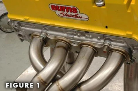
While working with Carobu Engineering LLC, we performed dyno testing on a Ferrari 3.0l, V-8 street engine as documented in Forza , October 2003 (Issue 48). During the tuning process we noted that the stock exhaust header inside diameter was slightly smaller than the exhaust port of the engine. With no other changes, except simply “porting” the exhaust header using a conventional die grinder, dyno tests showed approximately a 4 hp gain in peak power from 231hp to 235 hp. The smaller pipe formed a “dam” to exhaust flow resulting in flow-loss and reduced power. This test proved to me how critical this area is to the performance of a header.
So, when fitting the header pipe at the head, it is critical that the exhaust pipe be either “port-fit,” or slightly larger (0.030” or less) than the exhaust port for proper flow. The top of the port is the most critical section as this is typically the place of highest gas velocity during blowdown. It is best that the header tube be oriented parallel to the top of the port. Also, we prefer that the transition from the port to the primary tube be as smooth as possible over at least the top 90 degrees. Some header builders prefer the “step” at the port reasoning that the step will minimize back-flow or reversion. If this method is employed, the step should only be used at the bottom of the port.
In some cases we find that the exhaust port is larger than needed (usually over-zealous head-porters). Calvin from Elston Exhaust maintains that an area reduction of as much as 12% (sometimes more) can be had at the port in order to improve header scavenging. It is imperative that the transition from the port to the smaller tube is gentle, tapering over at least 1” length, and that there is no “wall” at the port. Also, you must be sure that the port is in-fact too large. Burns Stainless uses the X-design program as a guide for the expected size of the port.
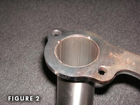
The technique used to attach the primary tube to the head flange is important from a mechanical standpoint, as this is a likely area for metal failure. Stress-risers should be avoided at all costs as they are a sure lead to pre-mature failures. A common mistake made by header builders, especially with thin-gage tubes, is when welding on the backside of a flange, too much penetration is used. The penetration results in a discontinuity in the tube that can lead to a stress fracture. Figure 1Jack Burns prefers to use a head flange that has a through-hole (Figure 2) the general shape of the port and slightly larger than the port (about 1-tubewall thickness around). Using the flange as a guide, he then shapes the header tube to the shape of flange. With the tube pushed all the way through the flange, he welds the tube to the flange from the head-side of the flange. There is little danger of too much weld penetration so a strong weld can be made. After the tube is welded, the entry into the header tube can be “ported” to match the port as discussed above.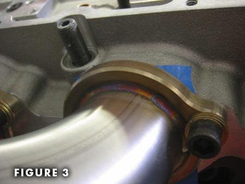
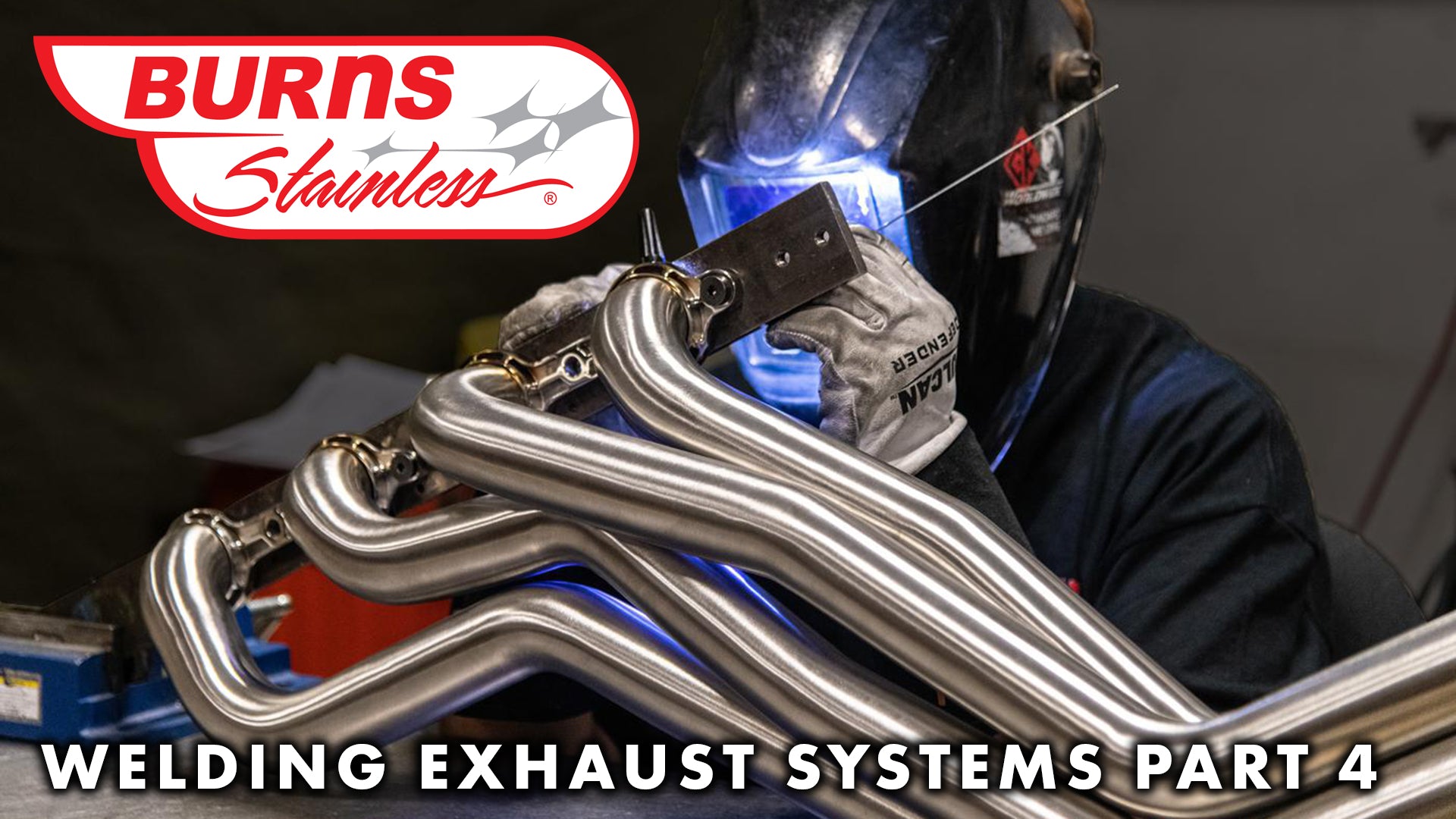
On the back-side of the flange, Jack prefers to weld/braze the joint utilizing a sili cone-bronze filler rod (Figure 3 - Courtesy of CPR Fabrication). This technique has been successfully used in NASCAR Cup headers for many years. The lower welding temperature of this process makes it less likely to over penetrate. In addition, the softer bronze metal gives the weld joint some resilience helping absorb the vibrational energy transmitted from the engine and chassis. And finally, the smooth golden appearance of the silicone bronze gives the header a beautifully detailed look.
