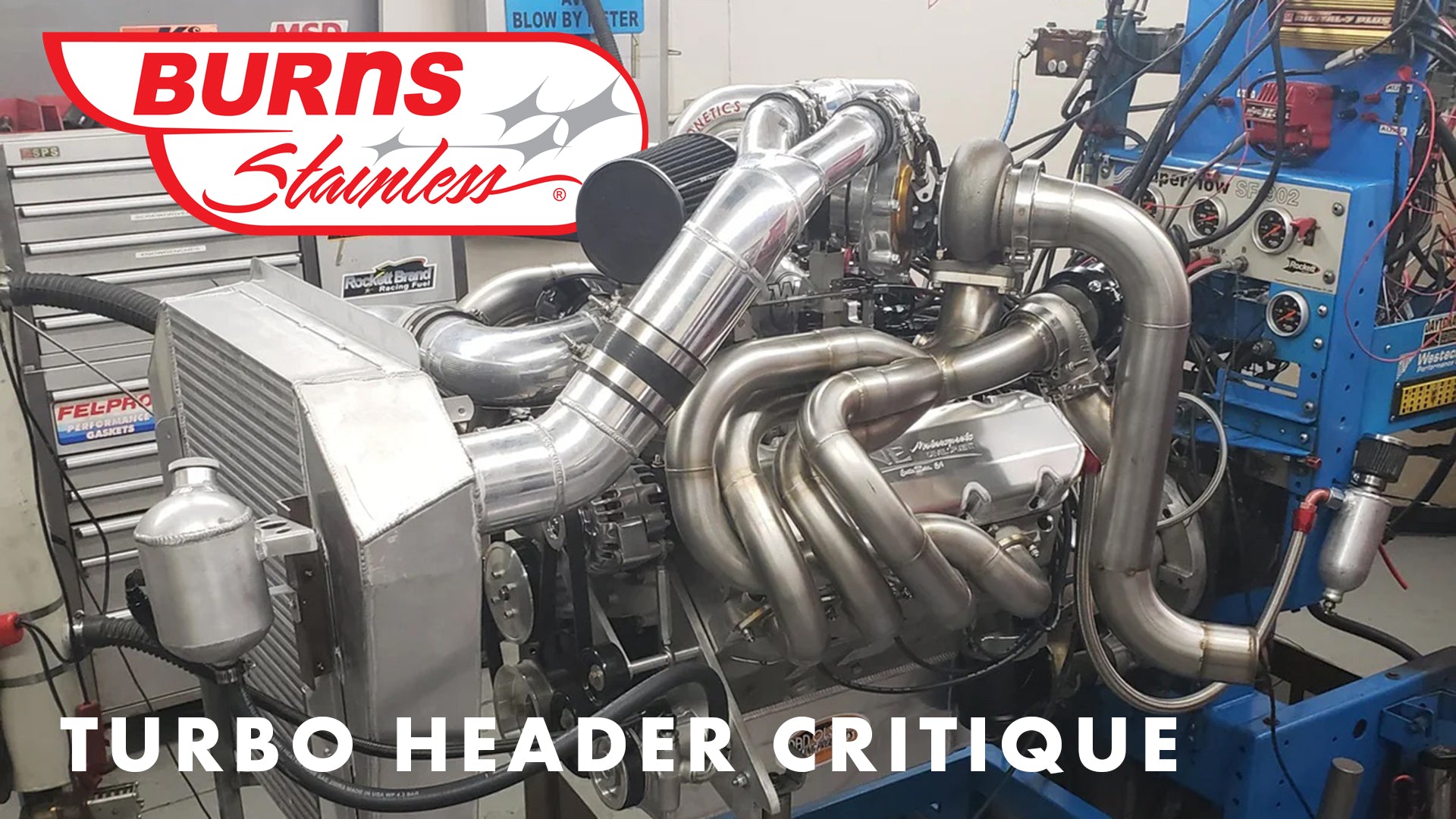
I went by DNE Motorsports to visit our friend Dave Ebbert, and saw a twin turbo big block project on his engine stand that had our exhaust parts . We do not always get a chance to see the final product, so this was a treat. The engine is a 540 cid big block Chevy with a pair of T4 88 mm Precision turbos built for a Pro-Street Truck (Figure 1).

As is typical for a job like that, there are many moving parts, multiple constraints and many hands in the pie. Also, projects like these can suffer from mission creep. Initially, this was to be a 900 hp grocery getter, then it morphed to an 1800 hp street/drag truck and ending up at 1300 hp truck with full finished mahogany liner that can make runs to Las Vegas.
Without careful planning and execution, problems can arise. In general, this system is a very good turbo exhaust system. There are many great features as well as a couple of areas that could have been done better.
The headers are 2-1/4” OD with a pair of Burns merge collectors. The builder used CNC machined header flanges made from 304SS. The flange is 3/8” thick giving the header a solid foundation. The primaries were fabricated from 16g, 321 stainless steel which we recommend for turbo applications. The layout of the primaries is very good.
The forward sweep of the headers provide a U-shaped “free-end” which minimizes stress in the header caused by thermal expansion (Figure 2). We prefer to see equal length headers, which these are not. But it is easy to criticize when it is out of the vehicle!

A couple of items that may not be evident from the photos but are important to consider. Some of the header bolts are hard to access to remove the headers. This is with the engine on an engine stand, much less trying to reach them installed in the vehicle.
Also, the header on the right side makes it impossible to remove the valve cover without removing the header (Figure 3). Combined with the hard to access header bolts, I can imagine that in the future, there will be a few curse words and wrenches sailing through the shop.

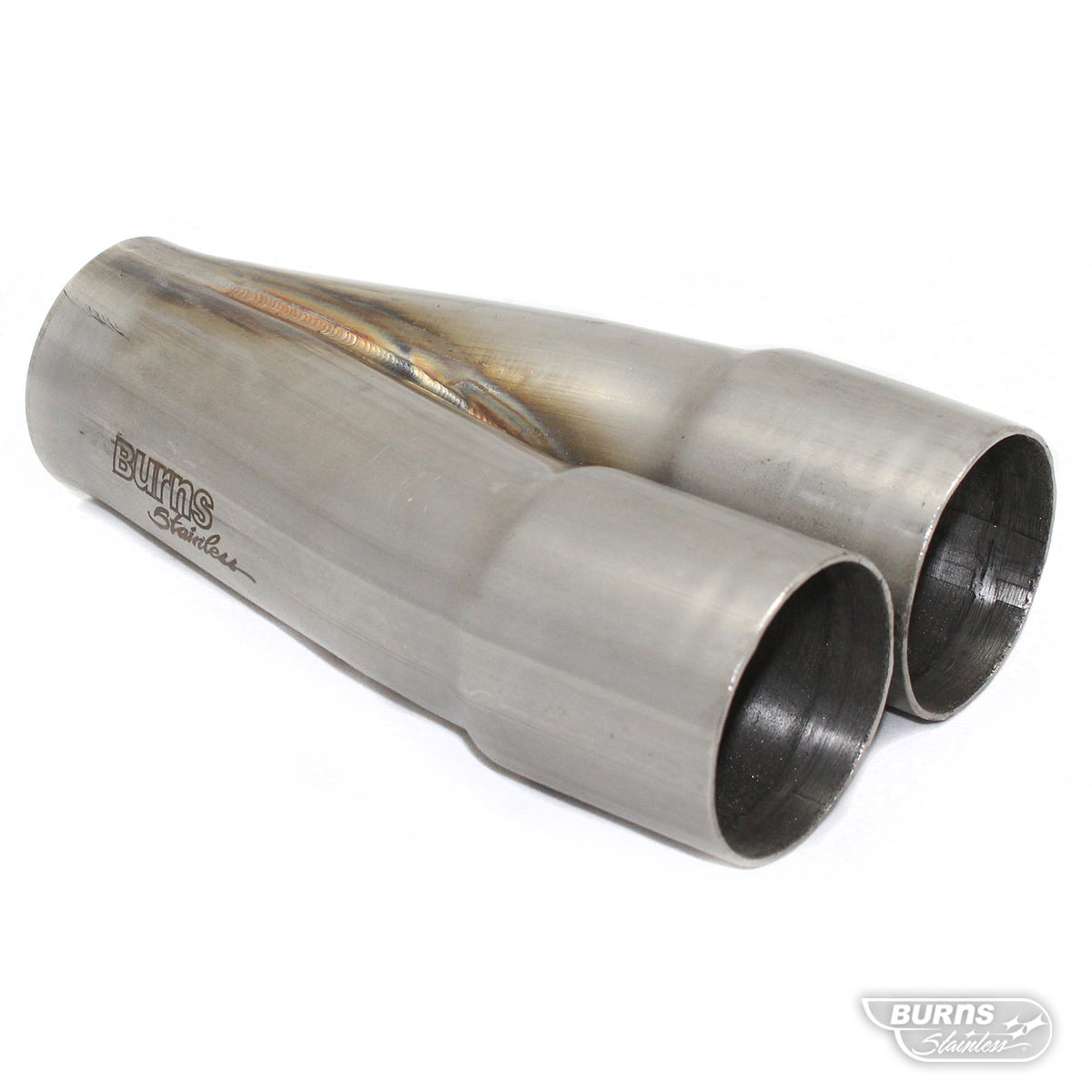
The collectors were supplied to the owner as double slip collectors which are used to help alleviate thermal stresses in the headers. The header fabricator, though very skilled, was unfamiliar with how they worked, so instead, he welded them solid to the primaries (Figure 4).

Though this is often the way turbo headers are built, it can lead to failures in the tubes or collectors since the vibration and thermal stress can begin causing stress fractures in the exhaust. Double slip collectors allow for relief of these stresses through the double walled slips in the collector.
It is important that the turbos are supported by something other than the headers. It has been standard practice in the import world to build exhausts from thick walled pipe which can support weight of turbos.
But when using thin walled tubing to save weight that is unacceptable. Though not seen in these photos, the fabricator will be installing some support rods using heim joints to allow for some flexibility.
The fabricator did an excellent job with how he plumbed the wastegate (Figure 5). Many turbo waste gates are plumbed at a 90 degree to the exhaust flow. This is often necessary due to space-constraints, but gives you poor boost control. The best way to plumb the wastegate tube is at an angle to the flow so the exhaust gas has a smooth direct path to the wastegate. To go one better, for low boost/high-wastegate flow situations, preference should be given to the wastegate as at high rpm, the wastegate flow can be more than the turbo flowrate. For High-boost applications, preference should be given to the turbo inlet. The fabricator did a beautiful job fitting all the tubes together at the wastegate.

The turbo exhaust plumbing has a shortcoming that I would like to discuss. The turbo outlet is setup for a 3.5” OD tube. Our recommendation is to expand out of the turbo using a transition, and in this case to 4” OD tubing.
Due to space constraints in the vehicle, only a 3” down tube could be fit, so the fabricator was forced to use 3” OD tubing. Again, recalling the initial goal of 900 hp, this would have probably been enough tube. But for the revised goal of 1800 hp, it simply was not enough, and dyno testing confirmed it.
When testing with the downtube shown, the turbos supplied 8.9 psi boost, but the exhaust backpressure was 14.5 psi and the motor made 949 hp. When the downpipe was replaced with a 4” downpipe power came up to 1038 hp at 8.5 psi boost and 12.5 psi exhaust pressure with no other changes.
We also would like to see the wastegate flow to be introduced into the exhaust further downstream of the turbo to minimize backpressure in the system. In fact, due to the space issues in the vehicle, the twins-wastegates will have dedicated exhaust tubes. This will allow the turbo a freer exhaust with adequate flowrate.
Further tuning resulted in 1300 hp – a little shy of the 1800 hp dream, but it will make one heck of a Interstate cruiser, and not a bad grocery getter.