Building stainless steel racing headers is not a “cut it, tack it, hope it clears” project. That kind of thinking belongs on bargain-bin parts, not on a serious race engine. A properly designed header controls exhaust velocity, supports scavenging, fits the chassis, survives heat, and makes power where the engine needs it.
That starts before the first piece of tubing hits the saw.
At Burns Stainless, we have spent decades helping engine builders, race teams, and fabricators build exhaust systems that are engineered, not guessed into place. Whether you are building custom racing headers for a road race car, drag car, off-road truck, motorcycle, marine application, or high-performance street machine, the same rule applies:
Plan the header before you sacrifice the tubing.
Start With the Header Design
The first decision is the design. If there is an existing, proven header design for your engine, chassis, and performance goal, use it as a foundation. There is no prize for reinventing a working solution unless the engine, packaging, rpm range, or power target demands it.
When a proven design exists, the process is more direct. You can move into building the actual stainless-steel header with confidence because the major design questions have already been answered. But don’t fall into the trap of monkey see, monkey do. Just because a competitor went fast with a particular exhaust design with his combination, it doesn’t mean you will with your combination.
But if you are starting from scratch, stop pretending the first tube layout in your head is engineering. It is not. Fresh header design requires real data, real experience, and a clear understanding of the engine combination.
That is where Burns Stainless earns its keep.
Our X-design parametric computer header design program helps determine a logical starting point for primary tube diameter, step sizing, collector configuration, and overall header layout. To use it, complete the Burns Stainless Race Engine Specification Form and send it in, or use the online form.
Engine builders with years of dyno experience may already know what they want. Good. That experience matters. But even experienced builders benefit from exhaust design direction because header tuning is a complex field.
Primary length, tube diameter, collector design, camshaft profile, displacement, rpm range, compression, and intended use all work together. Ignore one, and the engine will tell on you.
Mock It Up Before You Waste Stainless
In most custom header builds, the smart move is to create a mock-up header in mild steel before committing to stainless steel. Mild steel is easier to cut, fit, and adjust. It is also far less expensive than stainless. There are also great kits such as the ICE Engine Works kit that has plastic blocks that can be used to mockup headers.
Use the same radius mandrel bends in mild steel that you plan to use in the final stainless header. Do not mockup with random bends and expect the final product to magically match. A bend radius may change during the mock-up stage, and that change will directly affect the stainless bends required for the finished header.
This is where careful builders separate themselves from parts hangers.
A proper mock-up lets you solve routing, clearance, primary length, collector location, flange alignment, spark plug access, bolt access, chassis interference, and serviceability before the expensive material gets touched.

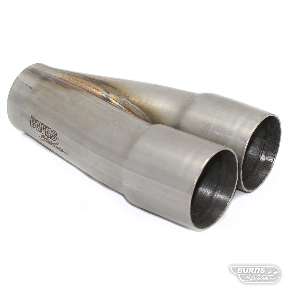
Build Mock Collectors First
Before starting the header mock-up, make mock collectors. They are simple, cheap, and useful.
Use steel tubing that is one size larger than the final primary tube diameter, typically 1/8-inch larger, with 18 gauge / .049-inch wall thickness. For example, if the final primary tube is 1-3/4-inch 16 gauge / .065-inch wall, use 1-7/8-inch 18-gauge tubing for the mock collector.
Cut short 2-inch sections, square them, and tack weld them together into an array that emulates the slip joints of the actual collector.
Mock collectors give you two major advantages. First, you can begin the header mock-up while the real Burns Stainless merge collectors are being built. Second, they let you leave the primary tubes long for exact trimming later.
The mock collector can be mounted solidly to the chassis, bellhousing, engine plate, or another fixed reference point while building headers in the car. It can also be used as an alignment tool when building headers on the bench.
Once the mock-up header has been built in the chassis, it can be transferred to a cylinder head mounted on the bench or an engine block on a stand. From there, the mock collector can be slipped onto the primary tubes and used to verify alignment.
Use Flexible Tubing Only for Rough Layout
If you are not using an ICE Engine Works or similar kit, laying out a prototype tube pack, flexible tubing can help visualize the general routing. Vacuum cleaner hose or similar tubing in approximately the same diameter as the final header tube can be useful for rough planning.
But do not fool yourself. Flexible hose is not a header tube.
It can help you see the general path, but the actual mandrel bends must be used for final mock-up, tube size planning, and material ordering. Flexible hose will not tell you the truth about bend radius, tangent cuts, joint fitment, or real-world packaging.

Equal-Length Primaries Are Earned
When designing the tube routing, consider equal-length primary pipes. A tolerance of ± 1/4-inch is a strong target.
That sounds simple until you try it.
Equal-length headers require patience, planning, and discipline. It is easy to get one primary tube looking clean. It is much harder to make all tubes fit the chassis, clear critical components, meet the collector cleanly, and land within tight length tolerance.
When equal-length primary pipes are achieved, it is the mark of an accomplished header fabricator.
Measure Tube Length from the Centerline
Tube length must be measured along the centerline of the bend. Not the inside radius. Not the outside radius. Not wherever the tape happens to sit.
Use a 1/4-inch-wide steel tape measure. A 3-foot tape is usually fine. Keep the tape flat and carefully move it on the neutral plane as the bend changes plane. Hold the tube in a vise or clamp when measuring and sight directly over the centerline.
After measuring a section, mark the length with a felt-tip marker. Then rotate the tube as needed and continue measuring to the end. Walk the tape around the bend in 1/2-inch to 3/4-inch intervals, rotating it under your finger as you go.
Measure twice. Then measure from the opposite end. Do not move forward until both measurements are within 1/8-inch.
That sounds fussy because it is.
Header fabrication rewards fussy.

Check the Flange Before Building Tubes
Before starting the mock-up header, check the flange alignment on the cylinder head.
Look for proper centering on the port. Confirm that the flange hole is sized correctly, slightly larger than the port to allow for tubing wall thickness. If the mounting studs or bolts have sloppy fitment, use a positive locating device. Roll pins or stud dowels can help lock in proper alignment.
As primary tubes get smaller and stepped header designs become more common, the flange-to-port interface becomes even more important. This area deserves the same respect as an intake manifold port match.
Also check gasket fitment at this stage. A bad gasket match can sabotage an otherwise clean header build.
The tubing section coming off the head flange must be aligned with the port. Do not cheat the tube side-to-side, up, or down just because it makes the rest of the routing easier. The top of the exhaust port should be parallel to the top of the header tube to provide the gases with a smooth transition from the port to the pipe. Drag losses can be significant since the velocity of the gases is highest at this point.
Think of the flange and tube interface as an extension of the exhaust port.
A straight section or slight upward angle with the direction of port flow is preferred when possible. A cheated radius at the flange disrupts exhaust flow and costs power. Many headers are built this way because it is easier. Easy is not the same as right.
While you are there, check practical access. Header bolts must be installable and removable with a wrench or socket. Spark plugs and plug sockets must clear the tubes. If the header cannot be serviced, the design is not finished.
No Cheated Radii. No Lazy Joints.
A cheated tube radius happens when a tubing bend is not cut perpendicular to the tangent line. The tangent line is perpendicular to the bend radius. A cut that is off tangent will not follow the true radius.
Every time two tubes are joined, check that they are aligned, on-plane, and tangent. Cheated joints create flow restriction. Sometimes packaging leaves no perfect choice, and a small compromise may be unavoidable. But those compromises should be identified during mock-up, not discovered after the stainless is tacked together.
Use the mock-up stage to eliminate as much cheating as possible.
Whenever possible, use a bend with a straight section attached instead of piecing a tube together with extra weld joints. Fewer welds usually make a cleaner, stronger, more professional header.
Transfer the Mock-Up to Stainless Carefully
When transferring the design from mild steel to stainless, lay the prototype tube over the stainless bend to mark the cut line. Do this on a well-lit workbench. You need to look directly down over the prototype to locate the witness line accurately.
Align the bend, then mark a line about 1/2-inch below the joint. Carefully extend the cut line so it remains tangent for the actual cut. Leave about 1/4-inch extra length for final tune-ups.
Measure the prototype section and compare it with the new stainless piece before cutting. If the lengths do not match, fix the witness line. Do not force the build forward.
Witness lines are also used when preparing two tubes for tacking. Clocking is critical. Make three witness lines across the joint so the tubes can be removed from the setup, tacked, and realigned correctly.
After tacking, recheck the tube alignment in the setup. Always.

Cutting Stainless Steel Requires Control
Cutting stainless tubing is one of the trickier parts of header fabrication. There are several ways to do it, but the method must provide speed, control, and repeatability.
Burns Stainless recommends a 14-inch two-wheel band saw running near friction-cutting speeds. Our setup uses a modified 14-inch band saw with a 1725 rpm electric motor, a 2.5-inch motor pulley, and a 6-inch wheel pulley, resulting in a blade speed of approximately 2633 SFPM.
A 1-1/2 to 2 horsepower motor is recommended to provide enough torque. Stainless can bog down a 1 hp motor. Carbon steel blades can provide good service life, especially 14 teeth per inch, 1/2-inch width, raker set blades.
This setup cuts fast, so be careful. It does not offer the same control as a slower saw. Line up the cut mark and watch for blade deflection.
For marking straight tubing, use a hand-held tubing roll cutter to score the witness line first.
Odd cuts, especially on larger diameter tubing, can be handled with a 14-inch abrasive cutoff saw. A cold saw with a fine-tooth steel blade works well for cutting straight tubing from stock. Because those cuts are true, they can usually be deburred and prepared for tacking with minimal adjustment.
For cutting off tack welds, use a die grinder with a small abrasive wheel. A hacksaw can also work. The goal is to barely break through the tack without damaging the joint face. Sometimes a light tap on the workbench is enough to break the tack free.

Grind Flat or Start Over
After a tube is cut, it must be ground to the correct length and angle. This is one of the most important parts of the entire build.
Use a bench or pedestal disc grinder, typically 12-inch to 20-inch diameter, to grind the cut surface flat. Do not make one side shorter than the other. Hold the tube at arm’s length and sight the joint surface against a well-lit background. Rotate the tubing 90 degrees in your hand and look for irregularities. A scribe line will help here.
If the angle is off, it will show.
This is eyeball engineering, and it takes practice. It is also where experienced fabricators stand apart from beginners. Use a straight section of tube or a T-square as a reference to confirm that you are grinding tangent. Lay the cut surface on a flat area and check for air gaps.
Air gaps are not harmless. They are evidence of poor fitment.
Round the Tube Before Fitting
When a stainless bend is cut, the cut section is often not perfectly round. That is normal. It is also something that must be corrected before fitting the tubes. Although normal, the amount of ovality in a bend section depends greatly on the quality of the bends. Burns Stainless bends are some of the best available.
After grinding the tube flat, deburr the inside with a die grinder and spiral band abrasive, or with a round file. Deburr the outside with a belt sander.
Next, squeeze the wide portion of the out-of-round tube in a vise until the shape is close to round. Then use a T-dolly to hammer-form the tube into shape. Look down the tube opening and rotate it in your hands to check roundness. High and low spots can be corrected with a sheet metal hammer.
After reshaping the tube, touch the surface back up on the disc grinder. The act of making the tube round again can change the cut surface, so flatness must be checked again.
Then deburr again.
Then fit again.
Then repeat the process as many times as necessary. That is header fabrication.

Match Tube Diameters When Needed
Mandrel bending can slightly stretch the metal and reduce the diameter compared with a straight section of tubing. If two sections do not match properly, the smaller section must be expanded.
Use a tubing expander. Large electro-hydraulic units, like those found in many muffler shops, work well. Handheld expanders can also handle the small adjustments often needed in header fabrication.
Stainless steel has spring-back, so work slowly. It is easier to make tubing larger than smaller. Expand in small steps, then check for roundness and flatness again.

No Air Gaps in Stainless Header Fitment
One of the main reasons for all this attention to fitment is simple: when tacking and welding stainless steel, there should be no air gap between the pieces.
A good test is to hold the two pieces in tacking position and see if they rock. Even a slight rocking motion means the joint needs more work.
Do not weld around bad fitment and call it craftsmanship. That is not fabrication. That is damage control.

Tack Welding Stainless Header Tubes
It is usually best to clamp one tube section in a vise while holding the other tube in your hand. A machinist vise works well.
Align the witness marks carefully while centering the tubes. Use your fingers to feel the joint alignment 180 degrees apart, then rotate your hand 90 degrees and check again. There should be no overhang.
When TIG tack welding, use low amperage. The tack should be fused only, without filler rod. Tack quickly to avoid melting holes in the tubing. Keep the torch cup close to the tack afterward so the post-flow shielding gas helps prevent oxidation. Close tubing fit-ups make tacking easier. Gaps in the fitment can easily lead to blow throughs (ask me how I know).
Practice on sample pieces first. Set the amperage correctly and develop the technique before touching the actual header.
If you burn a hole while tacking, break the joint apart and regrind or replace the piece. Do not build failure into the header.

After the first tack, rotate the tube 180 degrees for the second tack. The two tube segments may spread apart after the first tack, so hold them tightly together while making the second tack. If the gap will not close, the pieces probably were not flat to begin with.
Break it apart. Fix it. Start again.
Two opposing tacks are usually enough until the entire header is tacked.
Two tacks also make it easier to break the tube apart if a change is needed. After final changes are complete, add two more tacks to each joint for a total of four tacks at roughly 90-degree intervals.
Use a freshly ground electrode with a long taper. For TIG welding, a 3/32-inch or 1/16-inch thoriated tungsten is commonly used, depending on the setup and tubing thickness.

Final Welding: TIG Is the Standard
For final welding, TIG is the preferred process. MIG can be used in some cases, but TIG gives the control, consistency, and finish expected in a serious stainless steel racing header.
Stainless behaves differently than mild steel. It has lower thermal conductivity and a greater coefficient of expansion, which means it distorts more around the weld area.
When welding a stainless header tube to a 3/8-inch stainless header flange, use the lowest practical heat setting. A good TIG weld on stainless should show a shiny gold color. Dark gray, dull welds usually indicate too much heat.
Control distortion with proper fixturing and cooling. Sturdy, non-flexible welding fixtures help keep the part stable, especially if the header is allowed to cool before being removed.
Avoid unnecessary preheat. It can increase distortion.

Use the Correct Filler Rod
Use an equal or higher grade of stainless filler than the material being welded.
For example:
- Welding 304 stainless: use 308 filler rod or wire
- Welding stainless tubing to a mild steel flange: use 309 filler rod
- Welding 321 stainless: use 347 filler rod because 321 filler rod is not commonly manufactured
For 18 gauge and 16-gauge tubing, .030-inch to .035-inch TIG rod is commonly used.
Weld beads should be slightly convex. They should not be concave.
Concave welds are not a badge of skill. They are a warning sign.
Back-Purging Stainless Headers
At welding temperature, stainless steel reacts with oxygen and forms oxides on the inside of the tube. Fabricators often call this sugaring or noogies. It looks ugly because it is ugly, and it is not just cosmetic.
Internal oxidation creates a rough, contaminated weld root. That can hurt flow and weaken the weld area.
Back-purging solves the problem by replacing the oxygen inside the tube with inert gas, usually argon. The tube is capped at both ends, and a low, continuous flow of argon is introduced during welding.
A properly back-purged stainless header produces a cleaner internal weld and a stronger finished part. If you are building a serious stainless steel racing header, back-purging is not optional in spirit. It is part of doing the job correctly.
When Back-Purging Is Not Possible
If back-purging cannot be performed, use welding flux on the backside of the weld area. SolarFlux Type B is commonly used for this purpose and can be brushed onto the backside of the weld area before welding.
Is flux a perfect replacement for a proper purge? No.
But when purging is not possible, it is a practical way to reduce oxidation and protect the weld root.
The Burns Stainless Standard
Building stainless steel racing headers is not beginner work. It demands design discipline, proper mock-up, precise measuring, clean cutting, flat grinding, tight fitment, correct welding technique, and respect for exhaust flow.
There are no shortcuts that do not show up somewhere.
- A lazy flange transition shows up in power loss.
- A cheated joint shows up in flow restriction.
- A poor fit-up shows up in the weld.
- A skipped purge shows up inside the tube.
- A rushed design shows up on the dyno.
That is why serious builders start with a real plan and quality components.
Burns Stainless supplies the stainless tubing, merge collectors, fabrication components, and exhaust design experience used by racers, builders, and fabricators who do not want to build the same header twice.
Build it right the first time.
Or build it again.
Recommended Tool List
- Felt tip pen with rounded point
- Tape measure, 1/4” wide, 3 feet long
- Vise, 6” with soft jaws
- Machinist vise
- T-dolly
- Metal forming hammer
- Deburring tools
- Die grinder with sanding drum
- Half round file
- Belt sander
- Small vise grips with needle nose jaws
- Cutting Tools
- Band saw
- Abrasive cut-off saw
- Cold saw
- Hack saw
- Die grinder with abrasive disc
- Welder - TIG is preferred
- Tubing expander
- Tubing cutter ( for marking )
- T-square